PAUT for welds, castings & forgings, and pipes – mobile on-site or in our test lab. Accredited & documented.

Phased Array - PAUT

PAUT for welds, castings & forgings, and pipes – mobile on-site or in our test lab. Accredited & documented.

Request now
  • Manual testing – mobile or in-lab
  • Contrast methods & immersion
  • 2D / 1.5D / S/E sensors
  • Angle beam sensors & Cobra Scan
  • Digital image evaluation & reports

Non-destructive

Phased Array Ultrasonic Testing (PAUT)

Schematic of Phased Array Ultrasonic Testing (PAUT) on a weld.

Phased Array testing – schematic

Phased Array is the modern, imaging evolution of ultrasonic testing. Zeros GmbH performs PAUT on-site or in-lab — ideal for welds, castings & forgings, pipes as well as thickness/coating measurements on accessible and hard-to-reach geometries. Our reports are fully documented and support your quality assurance.

Why partner with Zeros?
  • Accredited test lab to DIN EN ISO/IEC 17025
  • PAUT on-site & in-lab — including Cobra Scan & immersion
  • High resolution via electronic focusing & sector scanning
  • Documented image evaluation for traceability
  • Experience in serial and single-part inspections
Applications
  • Weld testing on steel structures, vessels and piping
  • Castings & forgings, semi-finished products & profiles
  • Thickness measurement, corrosion mapping, flaw detection
  • Components with restricted access (e.g. inner surfaces)

Ergänzende Verfahren

Das Prüflaboratorium erfüllt die Anforderungen gemäß DIN EN ISO/IEC 17025.

FAQ

Frequently Asked Questions

Is Ultrasonic Testing Non-Destructive?

Yes, ultrasonic testing (UT) is a non-destructive testing (NDT) method. High-frequency sound waves are introduced into the component to detect defects and inhomogeneities within the material without damaging or altering the part. After testing, the component remains fully functional, allowing 100% material inspection during manufacturing or in-service inspections. Therefore, ultrasonic testing is a standard method used in quality assurance.

What does an ultrasonic tester do?

An ultrasonic tester performs non-destructive testing on components by sending ultrasonic waves into the material using a probe. The tester moves the probe manually or automatically across the component while monitoring the device display to detect irregularities such as cracks or voids. The tester documents and evaluates the results according to applicable standards, ensuring quality control of materials and components during manufacturing or maintenance.

Which components can be tested with ultrasonic testing?

Ultrasonic testing can be used to inspect all components and materials that are transmissive to ultrasound, such as metals, plastics, and composites. The suitability depends on the acoustic impedance and sound hardness of the material. In cast and forged components, manufacturing-related inhomogeneities can be detected immediately after production. Weld seams can be tested from a wall thickness of 8 mm using conventional ultrasonic testing, and from 6 mm using phased array techniques. Zeros GmbH also has extensive experience in project-specific validations to reliably inspect components with wall thicknesses below 6 mm using phased array technology.

What is Ultrasonic Testing (UT)?

Ultrasonic testing (UT) is a non-destructive testing method used to detect defects and measure wall thickness in materials. High-frequency sound waves generated by an ultrasonic device are transmitted into a material. When these waves encounter irregularities such as cracks, inclusions, or voids in components or welds, they are reflected. The reflected signals are captured and analyzed to determine the position, size, and type of defects. As a volumetric testing method, UT allows the internal inspection of materials like metals, plastics, and composites and is widely used in quality control.

Which Ultrasonic Testing Methods Exist?

Various ultrasonic testing methods are available for non-destructive material testing. These include conventional ultrasonic testing, phased array testing, and TOFD (Time of Flight Diffraction). The best method depends on factors such as the material, manufacturing process, wall thickness, defect detection limit, and the desired documentation. While conventional UT is sufficient for many standard inspections, phased array and TOFD offer advanced options for representation and evaluation of defect indications. We are happy to advise you on which method is best suited for your testing project.

Why is ultrasonic testing used in materials testing?

Ultrasonic testing is used in materials testing because, as a non-destructive method, it enables reliable quality assurance. Compared to other volumetric testing methods such as radiographic testing, UT is often a more cost-effective and flexible solution. It can detect internal defects like cracks, inclusions, or voids early without damaging the component. UT can be used on-site, requires no complex radiation protection measures, and provides immediate, interpretable results. Additionally, ultrasonic testing allows for precise wall thickness measurements and can be applied to a wide range of materials such as metals, plastics, and composites. These advantages make UT an essential part of non-destructive testing in both manufacturing and maintenance.

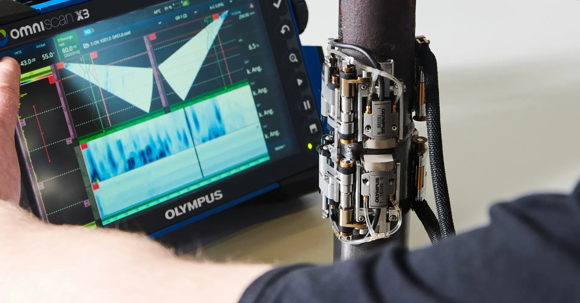
Technical fundamentals of Phased Array Ultrasonic Testing (PAUT)

PAUT principle: phased excitation and focused sound field
Operating principle

In Phased Array (phased array technology), the individual elements of a multi-channel probe are excited with phased time delays. These delays allow electronic control of angle, focal depth, focal length and beam diameter of the sound field. Echoes from a desired focal point are received coherently with corresponding delays — resulting in high-resolution S-, B-, and C-scans.

Advantages over conventional UT
  • Faster area coverage through electronic beam steering
  • Higher detection sensitivity via dynamic depth focusing (DDF)
  • Imaging representation for thorough evaluation & documentation
  • Better adaptability to complex geometries
Phased Array sensor
Scan modes

Electronic linear scan (linear scan): An active element group shifts the aperture along the sensor axis — ideal for fast, parallel area coverage.

Sector scan (angle scan): The sound beam is swept over an angular range; focus & excitation conditions are definable — preferred for weld inspections.

Dynamic depth focusing (DDF): Real-time adjustment of delay and gain on reception — improves signal-to-noise ratio and detection sensitivity throughout the thickness.

Sensors & aperture

We use angle beam sensors, 2D/1.5D sensors, and S/E sensors — depending on component geometry with delay wedges, in contact or immersion technique. The active aperture (A) of a linear sensor is given by A = (n‑1)·p + e (n elements, p pitch, e element width) and significantly determines resolution & penetration depth.

Data representation & documentation

PAUT provides S-, B-, and C-scans with color-coded amplitude display. All results are digitally recorded and compiled in a tamper-proof test report — including image evaluation and assessment criteria.

Mirror effect for wall and coating thickness measurement

Schematic of the mirror effect
How it works

The so-called mirror effect records ultrasonic echoes between the front and back walls of a component. The time difference of these echoes enables precise determination of wall or coating thickness.

This method is especially useful for corrosion inspections, monitoring of pipelines, inspection of vessels, and components with coatings. Thanks to the imaging capability of Phased Array, even complex geometries can be reliably evaluated.

Scan modes & typical use cases

The choice of scan mode depends on geometry, material and objective. The overview shows common settings in practice.

Mode Typical application Advantage
Linear‑Scan Semi-finished products, plates, profiles; area coverage Fast & reproducible
Sector scan Welds on pipe/vessel; angle range Volume coverage & angle flexibility
DDF Varying thickness; fine defects over depth High sensitivity over full thickness
Immersion technique High-resolution analytics; complex contours Very high resolution, uniform coupling